Saturday, May 23, 2020

Francis Turbine

Francis Turbine


Turbines using the impulse action of water are the best ones. No it’s not like that reaction turbines are more efficient, when all of this was happening, James B. Francis, an American civil engineer comes up with his turbine called Francis turbine,  both the impulse and reaction turbine, say water enters the turbine radially and exits axially. But that’s not a secret to his turbine efficiency. The magic lies in his amazing design of blades, these blades rotate using both reaction and impulse force of water flowing through them.


The ability of francis turbine to use both the kinetic and potential energy to produce power, shorts out a major problem of water head availability as it could be used efficiently for head as low as 50m to as high as 400m and also for a wide range of flow rates which could be as low as 10 meter-cube per second to as high as 700 meter-cube per second.


That’s why Francis turbine is also called as mixed flow turbine. so it is now obvious that it is the best modern turbine we have till date. It is the most widely used turbine in the hydro-power plants. So let’s just figure it out what else it contains which makes it stand out of league of all other turbines.


Main Components


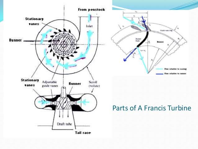
The Various main components of francis turbine are:


Francis turbine diagram of main components


Image source


1. Spiral casing


It is a spiral casing, with uniformly decreasing cross- section area, along the circumference. Its decreasing cross-section area makes sure that we have a uniform velocity of the water striking the runner blades, as we have openings for water flow in-to the runner blades from the very starting of the casing, so flow rate would decrease as it travels along the casing. So we reduce its cross-section area along its circumference to make pressure uniform, thus uniform momentum or velocity striking the runner blades.


2. Stay vanes


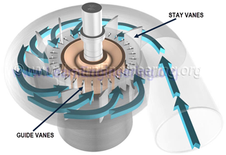
Stay vanes and guide vanes guides the water to the runner blades. Stay vanes remain stationary at their position and reduces the swirling of water due to radial flow, as it enters the runner blades. Thus making turbine more efficient.


3. Guide vanes 

Water after passing through stay vanes, glides through guide vanes to enter the runner blades. Guide vanes can change their angle thus can control the angle of attack of water to the runner blades, making them work more efficiently. Moreover they also regulate the flow rate of water into the runner blades thus controlling the power output of a turbine according to the load on the turbine.


4. Runner blades


Design of the runner blades decides how well a turbine is going to perform. So runner blades of mixed flow turbine can be divided into two parts, the upper part of the blades use the reaction force of water flowing through it and the lower half is in the shape of a small bucket using the impulse action of water flowing through it. These two forces together makes the runner to rotate.


5. Draft tube

Draft tube connects the runner exit to the tail race. Its cross-section area increases along its length, as the water coming out of runner blades is at considerably low pressure, so its expanding cross-section area help it to recover the pressure as it flows towards tail race.


Working Principle


Francis turbine blades are designed in such a way that one portion of the blade design creates the pressure difference between the opposite faces of the blade when water flows through it, and the remaining portion’s blade design use the impulse force of water hitting it and this combined action of pressure difference and impulse force generates enough power to get turbine moving at a required speed. Thus there would be a decrease in both kinetic energy and potential energy of water at exit, then what it has when it enters the turbine.


It is a clever design which uses both the reaction and impulse force to generate power output better than individual impulse turbine or reaction turbines could produce at same water head conditions.


Water enters the turbine through spiral casing, and starts entering the runner blades, passing through stay vanes and guide vanes, as it moves along the length of casing the decreasing cross-section area of the spiral casing makes sure that the pressure energy of water would remain uniform along its length, as a portion of water is also entering the runner blades, which would reduce its flow rate along the length of the casing. The stay vanes being stationary at their place, removes the swirls from the water, which are generated due to flow through spiral casing and tries it to make the flow of water more linear to be deflected by adjustable guide vanes. The angle of guide vanes decides the angle of attack of water at the runner blades thus make sure the output of the turbine. Guide vanes also controls the flow rate of water in-to the runner blades thus acting according the load on the turbine. The runner blades are stationary and can-not pitch or change their angle so it’s all about the guide vanes which controls the power output of a turbine.


Further-more the upper part of runner blades are designed in such a way that they use the pressure difference between the opposite faces of a blade created by water flowing through it, same as the air-foil uses the pressure difference to generate lift force. And the remaining part of the blade is designed like a small bucket, which makes use of water’s kinetic energy. Thus runner blades make use of both pressure energy and kinetic energy of water and rotates the runner in most efficient way.


The water coming out of runner blades would lack both the kinetic energy and pressure energy, so we use the draft tube to recover the pressure as it advances towards tail race, but still we cannot recover the pressure to that extent that we can stop air to enter into the runner housing thus causing cavitation.


Applications


Francis turbine is the most widely used turbine in hydro-power plants to generate electricity.


Mixed flow turbine is also used in irrigation water pumping sets to pump water from ground for irrigation.


It is efficient over a wide range of water head and flow rate.


It is most efficient hydro-turbine we have till date.


Friday, May 22, 2020

induction to turbines

Introduction to turbines

The hydraulic turbine is a prime mover that uses the energy of flowing water and converts  is  into  the  mechanical  energy  in  the  form  of  rotation  of  the  runner.  (A prime mover is a machine which uses the raw energy of a substance and converts it into the mechanical energy.) Since the fluid medium is water, these turbines are also known   as   the   ‘ water   turbines’ .   Hydraulic   turbines   coupled   with   hydro    — generators form the so  —called ‘ hydrounits’ which are widely used now a days for generating electrical power.


Classification of Hydraulic turbines:


1) Based on type of energy at inlet to the turbine:

Impulse Turbine : The energy is in the form of kinetic form. e.g: Pelton wheel, Turbo wheel.

Reaction Turbine : The energy is in both Kinetic and Pressure form. e.g: Tubular, Bulb, Propellar, Francis turbine.


2) Based on direction of flow of water through the runner:

Tangential flow: water flows in a direction tangential to path of rotational, i.e. Perpendicular to both axial and radial directions.

Radial outward flow e.g : Forneyron turbine.

Axial flow : Water flows parallel to the axis of the turbine. e.g: Girard, Jonval, Kalpan turbine.

Mixed flow : Water enters radially at outer periphery and leaves axially. e.g : Modern Francis turbine.


3) Based on the head under which turbine works:

High head, impulse turbine. e.g : Pelton turbine.

Medium head,reaction turbine. e.g : Francis turbine.

Low head, reaction turbine. e.g : Kaplan turbine, propeller turbine.


4) Based on the specific speed of the turbine:

Low specific speed, impulse turbine. e.g : Pelton wheel.

Medium specific speed, reaction turbine. e.g : Francis wheel.

High specific speed, reaction turbine. e.g : Kaplan and Propeller turbine.


5) Based on the name of the originator:

Impulse turbine – Pelton wheel, Girard, Banki turbine.

Reaction turbine – Forneyron, Jonval, Francis, Dubs, Deriaze, Thomson kalpan, Barker, Moody, Nagler, Bell.


Construction and Working principle of Pelton Wheel (Turbine)


Pelton Turbine is a Tangential flow impulse turbine in which the pressure energy of water is converted into kinetic energy to form high speed water jet and this jet strikes the wheel tangentially to make it rotate. It is also called as Pelton Wheel.


Parts and Their Functions of Pelton Turbine

Different parts and their functions of Pelton turbine are as follows


  1. Nozzle and Flow Regulating Arrangement

  2. Runner and Buckets

  3. Casing

  4. Braking Jet


  1. Nozzle and Flow Regulating Arrangement

The water from source is transferred through penstock to which end a nozzle is provided. Using this nozzle the high speed water jet can be formed. To control the water jet from nozzle, a movable needle spear is arranged inside the nozzle.


The spear will move backward and forward in axial direction. When it is moved forward the flow will reduce or stopped and when it is moved backward the flow will increase.


  1. Runner and Buckets

A Pelton turbine consists of a runner, which is a circular disc on the periphery of which a number of buckets are mounted with equal spacing between them. The buckets mounted are either double hemispherical or double ellipsoidal shaped.


A dividing wall called splitter is provided for each bucket which separates the bucket into two equal parts. The buckets are generally made of cast iron or stainless steel or bronze depending upon the head of inlet of Pelton turbine.


  1. Casing

The whole arrangement of runner and buckets, inlet and braking jets are covered by the Casing. Casing of Pelton turbine does not perform any hydraulic actions but prevents the splashing of water while working and also helps the water to discharge to the tail race.


  1. Braking Jet

Braking jet is used to stop the running wheel when it is not working. This situation arises when the nozzle inlet is closed with the help of spear then the water jet is stopped on the buckets. But Due to inertia, the runner will not stop revolving even after complete closure of inlet nozzle.


To stop this, a brake nozzle is provided as shown in figure 1. The brake nozzle directs the jet of water on the back of buckets to stop the wheel. The jet directed by brake nozzle is called braking jet.


Working of Pelton Turbine


The water is transferred from the high head source through a long conduit called Penstock.


Nozzle arrangement at the end of penstock helps the water to accelerate and it flows out as a high speed jet with high velocity and discharge at atmospheric pressure.


The jet will hit the splitter of the buckets which will distribute the jet into two halves of bucket and the wheel starts revolving.


The kinetic energy of the jet is reduced when it hits the bucket and also due to spherical shape of buckets the directed jet will change its direction and takes U-turn and falls into tail race.

Water Jet striking Pelton Wheel Buckets.


 Water Jet striking Pelton Wheel Buckets


In general, the inlet angle of jet is in between 1o to 3o, after hitting the buckets the deflected jet angle is in between 165o to 170o.


The water collected in tail race should not submerge the Pelton wheel in any case.


To generate more power, two Pelton wheels can be arranged to a single shaft or two water jets can be directed at a time to a single Pelton wheel


Saturday, May 16, 2020

Construction and Working principle of Receprocating Pump

Construction and Working principle of Receprocating Pump

What is a Reciprocating Pump?

Reciprocating pump is a positive displacement pump where certain volume of liquid is collected in enclosed volume and is discharged using pressure to the required application. Reciprocating pumps are more suitable for low volumes of flow at high pressures.


Components of Reciprocating Pump

  • Suction Pipe

  • Suction Valve

  • Delivery Pipe

  • Delivery Valve

  • Cylinder

  • Piston and Piston Rod

  • Crank and Connecting Rod

  • Strainer

  • Air Vessel


  • Suction Pipe

Suction pipe connects the source of liquid to the cylinder of the reciprocating pump. The liquid is suck by this pipe from the source to the cylinder.


  • Suction Valve

Suction valve is non-return valve which means only one directional flow is possible in this type of valve. This is placed between suction pipe inlet and cylinder. During suction of liquid it is opened and during discharge it is closed.


  • Delivery Pipe

Delivery pipe connects cylinder of pump to the outlet source. The liquid is delivered to desired outlet location through this pipe.


  • Delivery Valve

Delivery valve also non-return valve placed between cylinder and delivery pipe outlet. It is in closed position during suction and in opened position during discharging of liquid.


  • Cylinder

A hollow cylinder made of steel alloy or cast iron. Arrangement of piston and piston rod is inside this cylinder. Suction and release of liquid is takes place in this so, both suction and delivery pipes along with valves are connected to this cylinder.


  • Piston and Piston Rod

Piston is a solid type cylinder part which moves backward and forward inside the hollow cylinder to perform suction and deliverance of liquid. Piston rod helps the piston to its linear motion.


  • Crank and Connecting Rod

Crank is a solid circular disc which is connected to power source like motor, engine etc. for its rotation. Connecting rod connects the crank to the piston as a result the rotational motion of crank gets converted into linear motion of the piston.


  • Strainer

Strainer is provided at the end of suction pipe to prevent the entrance of solids from water source into the cylinder.


  • Air Vessel

Air vessels are connected to both suction and delivery pipes to eliminate the frictional head and to give uniform discharge rate.


Working of Reciprocating Pump

The working of reciprocating pump is as follows:


When the power source is connected to crank, the crank will start rotating and connecting rod also displaced along with crank.


The piston connected to the connecting rod will move in linear direction. If crank moves outwards then the piston moves towards its right and create vacuum in the cylinder.


This vacuum causes suction valve to open and liquid from the source is forcibly sucked by the suction pipe into the cylinder.


When the crank moves inwards or towards the cylinder, the piston will move towards its left and compresses the liquid in the cylinder.


Now, the pressure makes the delivery valve to open and liquid will discharge through delivery pipe.


When piston reaches its extreme left position whole liquid present in the cylinder is delivered through delivery valve.


Then again the crank rotate outwards and piston moves right to create suction and the whole process is repeated.


Generally the above process can be observed in a single acting reciprocating pump where there is only one delivery stroke per one revolution of crank. But when it comes to double acting reciprocating pump, there will be two delivery strokes per one revolution of crank.


Thursday, May 14, 2020

Construction and Working Principal of Centrifugal pump


Construction And Working Of Centrifugal Pump 


Centrifugal pumps are the most widely used of all the turbo machine (or rotodynamic) pumps. This type of pumps uses the centrifugal force created by an impeller which spins at high speed inside the pump casing.


CONSTRUCTION DETAILS OF A CENTRIFUGAL PUMP: 

Centrifugal pump is classified as the following:-


1. Stationary components


2. Rotating components


1. Stationary components of the centrifugal pump are the following:


a) Casing: – It is an air tight passage surrounding the impeller. It is designed in such a way that the kinetic energy of the water discharged at the outlet of the impeller is converted into pressure energy before the water leaves the casing and enters the delivery pipe.

 Types of Centrifugal pump casing:-

1) Volute casing: – It is spiral type of casing in which area of flow increase gradually. The increase in area of flow decreases the velocity of flow and increases the pressure of water.

2) Vortex casing: – if a circular chamber is introduced between casing and the impeller, the casing is known as vortex casing.

3) Casing with guide blades: – the impeller is surrounded by a series of guide blades mounted on a ring know as diffuser.


b) Suction pipe: – 

The pipe whose one ends is connected to the inlet of the pump and other end dip into water in a sump.

c) Delivery pipe: – The pipe whose one end is connected to the outlet of the pump and other end is involved in delivering the water at a required height.


2. Rotating component of the centrifugal pump is Impeller.


Impeller: – It is the main rotating part that provides the centrifugal acceleration to the fluid. 

Classification of impeller:

a) Based on direction of flow:

1)  Axial-flow: – the fluid maintains significant axial-flow direction components from the inlet to outlet of the rotor.

2)  Radial-flow: – the flow across the blades involves a substantial radial-flow component at the rotor inlet, outlet and both.

3) Mixed-flow: – there may be significant axial and radial flow velocity components for the flow through the rotor row.

b) Based on suction type:

1)  Single suction: – liquid inlet on one side.

2)  Double suction: – liquid inlet to the impeller symmetrically from both sides.

c) Based on mechanical construction:

1) Closed: – shrouds or sidewall is enclosing the vanes.

2) Open: – no shrouds or wall to enclose the vanes.

3) Semi–open or vortex type.


Working Of Centrifugal Pump


Water is drawn into the pump from the source of supply through a short length of pipe (suction pipe). Impeller rotates; it spins the liquid sitting in the cavities between the vanes outwards and provides centrifugal acceleration with the kinetic energy.


This kinetic energy of a liquid coming out an impeller is harnessed by creating a resistance to flow. The first resistance is created by the pump volute (casing) that catches the liquid and shows it down.

In the discharge nozzle, the liquid further decelerates and its velocity is converted to pressure according to BERNOULLI’S PRINCIPAL.

Introduction and component parts of Centrifugal pump

CENTRIFUGAL PUMPS 

As we know the pump is the hydraulic machine which converts mechanical energy into hydraulic which is in the form of pressure energy this conversion is done with the help of Centrifugal force or centrifugal effect then the Pump which is being used to do this conversion is called centrifugal pump.


A centrifugal pump is a rotodynamic pump that uses a rotating impeller to increase the pressure of a fluid. Centrifugal pumps are commonly used to move liquids through a piping system. The fluid enters the pump impeller along or near to the rotating axis and is accelerated by the impeller, flowing radially outward into a diffuser or volute chamber (casing), from where it exits into the downstream piping system. Centrifugal pumps are used for large discharge through smaller heads. 

Centrifugal pump use a rotating impeller to create vaccum in order to move liquid, impeller is also know as blade

CF have benefit from simple design with few moving parts resulting in lower maintain and costs.

Modern process plants use powerful centrifugal pumps, primarily because of the following factors : 
1. The low initial cost. 
2. Low maintenance costs. 
3. Simple in operation. 
4. Ability to operate under a wide variety of conditions. 
5. Give a smooth, continuous flow, free from pulsation. 

CENTRIFUGAL FORCE 

The centrifugal force is a outward force arising from the body;s inertia which body moves in a circular path,the force that acts away from the centers is called CF
The word, ' centrifugal ' is derived from the latin language and is formed from two words 
'centri' meaning 'centre' and 'fugal' meaning 'to fly away from'. 
Centrifugal - 'to fly away from the centre'.
This is the force developed due to the rotation of a body - solid, liquid or gas. The force of rotation 
causes a body, or a fluid, to move away from the centre of rotation. 

 Component pats of Centrifugal pump

There are a few components that virtually every centrifugal pump has in common. These components includes

Centrifugal pump is a hydraulic machine which converts mechanical energy into hydraulic energy by the use of centrifugal force acting on the fluid. These are the most popular and commonly used type of pumps for the transfer of fluids from low level to high level.

Its is used in places like agriculture, municipal (water and wastewater plants), industrial, power generation plants, petroleum, mining, chemical, pharmaceutical and many others.

1. Impeller

It is a wheel or rotor which is provided with a series of backward curved blades or vanes. It is mounded on the shaft which is coupled to an external source of energy which imparts the liquid energy to the impeller there by making it to rotate.


Open, Semi Enclosed and Enclosed Impeller.

Fig 2: Open, Semi Enclosed and Enclosed Impeller

Impellers are divided into 3 types,

  1. Open Impeller
  2. Semi enclosed Impeller
  3. Enclosed Impeller

2. Casing

It is a pipe which is connected at the upper end to the inlet of the pump to the centre of impeller which is commonly known as eye. The double end reaction pump consists of two suction pipe connected to the eye from both sides. The lower end dips into liquid in to lift. The lower end is fitted in to foot valve and strainer.

Main Components of Centrifugal Pump.

Fig 3: Main Components of Centrifugal Pump.

Commonly three types of casing are used in centrifugal pump,

  1. Volute Casing
  2. Vortex Casing
  3. Casing with Guide Blades

3. Delivery Pipe

It is a pipe which is connected at its lower end to the out let of the pump and it delivers the liquid to the required height. Near the outlet of the pump on the delivery pipe, a valve is provided which controls the flow from the pump into delivery pipe.

4. Suction Pipe with Foot Valve and Strainer

suction pipe is connected with the inlet of the impeller and the other end is dipped into the sump of water. At the water end, it consists of foot value and strainer. The foot valve is a one way valve that opens in the upward direction. The strainer is used to filter the unwanted particle present in the water to prevent the centrifugal pump from blockage.

Monday, May 11, 2020

Introduction to Pumps and Turbines

Introduction to Pumps

What is pump?

Pump is a hydraulic machine which convert the mechanical energy into hydraulic energy are called pumps.
 
I.e mechanical energy--to--Hydrauic Energy which is in the form of pressure energy