Introduction to turbines
The hydraulic turbine is a prime mover that uses the energy of flowing water and converts is into the mechanical energy in the form of rotation of the runner. (A prime mover is a machine which uses the raw energy of a substance and converts it into the mechanical energy.) Since the fluid medium is water, these turbines are also known as the ‘ water turbines’ . Hydraulic turbines coupled with hydro — generators form the so —called ‘ hydrounits’ which are widely used now a days for generating electrical power.
Classification of Hydraulic turbines:
1) Based on type of energy at inlet to the turbine:
Impulse Turbine : The energy is in the form of kinetic form. e.g: Pelton wheel, Turbo wheel.
Reaction Turbine : The energy is in both Kinetic and Pressure form. e.g: Tubular, Bulb, Propellar, Francis turbine.
2) Based on direction of flow of water through the runner:
Tangential flow: water flows in a direction tangential to path of rotational, i.e. Perpendicular to both axial and radial directions.
Radial outward flow e.g : Forneyron turbine.
Axial flow : Water flows parallel to the axis of the turbine. e.g: Girard, Jonval, Kalpan turbine.
Mixed flow : Water enters radially at outer periphery and leaves axially. e.g : Modern Francis turbine.
3) Based on the head under which turbine works:
High head, impulse turbine. e.g : Pelton turbine.
Medium head,reaction turbine. e.g : Francis turbine.
Low head, reaction turbine. e.g : Kaplan turbine, propeller turbine.
4) Based on the specific speed of the turbine:
Low specific speed, impulse turbine. e.g : Pelton wheel.
Medium specific speed, reaction turbine. e.g : Francis wheel.
High specific speed, reaction turbine. e.g : Kaplan and Propeller turbine.
5) Based on the name of the originator:
Impulse turbine – Pelton wheel, Girard, Banki turbine.
Reaction turbine – Forneyron, Jonval, Francis, Dubs, Deriaze, Thomson kalpan, Barker, Moody, Nagler, Bell.
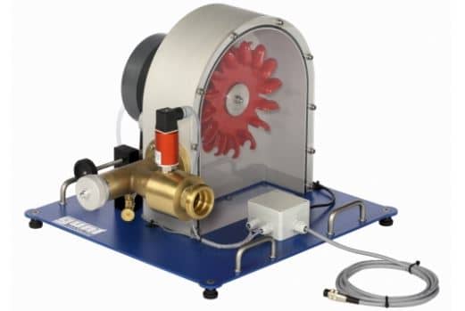
Construction and Working principle of Pelton Wheel (Turbine)
Pelton Turbine is a Tangential flow impulse turbine in which the pressure energy of water is converted into kinetic energy to form high speed water jet and this jet strikes the wheel tangentially to make it rotate. It is also called as Pelton Wheel.
Parts and Their Functions of Pelton Turbine
Different parts and their functions of Pelton turbine are as follows
Nozzle and Flow Regulating Arrangement
Runner and Buckets
Casing
Braking Jet
Nozzle and Flow Regulating Arrangement
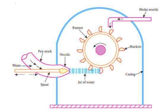
The water from source is transferred through penstock to which end a nozzle is provided. Using this nozzle the high speed water jet can be formed. To control the water jet from nozzle, a movable needle spear is arranged inside the nozzle.
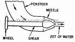
The spear will move backward and forward in axial direction. When it is moved forward the flow will reduce or stopped and when it is moved backward the flow will increase.
Runner and Buckets
A Pelton turbine consists of a runner, which is a circular disc on the periphery of which a number of buckets are mounted with equal spacing between them. The buckets mounted are either double hemispherical or double ellipsoidal shaped.
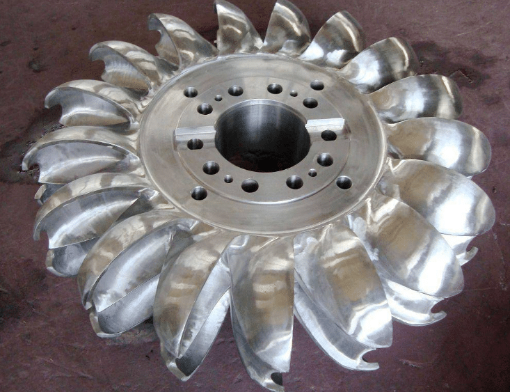
A dividing wall called splitter is provided for each bucket which separates the bucket into two equal parts. The buckets are generally made of cast iron or stainless steel or bronze depending upon the head of inlet of Pelton turbine.
Casing
The whole arrangement of runner and buckets, inlet and braking jets are covered by the Casing. Casing of Pelton turbine does not perform any hydraulic actions but prevents the splashing of water while working and also helps the water to discharge to the tail race.
Braking Jet
Braking jet is used to stop the running wheel when it is not working. This situation arises when the nozzle inlet is closed with the help of spear then the water jet is stopped on the buckets. But Due to inertia, the runner will not stop revolving even after complete closure of inlet nozzle.
To stop this, a brake nozzle is provided as shown in figure 1. The brake nozzle directs the jet of water on the back of buckets to stop the wheel. The jet directed by brake nozzle is called braking jet.
Working of Pelton Turbine
The water is transferred from the high head source through a long conduit called Penstock.
Nozzle arrangement at the end of penstock helps the water to accelerate and it flows out as a high speed jet with high velocity and discharge at atmospheric pressure.
The jet will hit the splitter of the buckets which will distribute the jet into two halves of bucket and the wheel starts revolving.
The kinetic energy of the jet is reduced when it hits the bucket and also due to spherical shape of buckets the directed jet will change its direction and takes U-turn and falls into tail race.
Water Jet striking Pelton Wheel Buckets.
Water Jet striking Pelton Wheel Buckets
In general, the inlet angle of jet is in between 1o to 3o, after hitting the buckets the deflected jet angle is in between 165o to 170o.
The water collected in tail race should not submerge the Pelton wheel in any case.
To generate more power, two Pelton wheels can be arranged to a single shaft or two water jets can be directed at a time to a single Pelton wheel
No comments:
Post a Comment